Advanced Vision Systems —
Increasing demand for data and bandwidth requires high-volume manufacturing of photonics and RF electronics at a level we have never seen before. In this post, we examine a specific feature required from these new levels of demand, Advanced Vision Systems.
Machine vision is critical for accurate placement. Having a proven ultra-accurate machine platform that is mechanically and thermally stable, with no cantilevered parts, is a baseline to achieve accurate device placement. In addition, the accurate alignment of device fiducials is required to achieve micron-level accuracies. Many other key features are required for accurate final placement.
Local and global vision alignment is used for nested substrates and feature alignment. The software must allow the user to align die relative to substrate fiducials, die edges, or features of previously placed die. The alignment of the laser chip to a photo diode or a lens to a VCSEL, are common photonics examples. Another example is the alignment of a critical die, such as with MMICs and beam lead diodes. This capability ensures repeatability and precise alignment of optical and microwave devices.
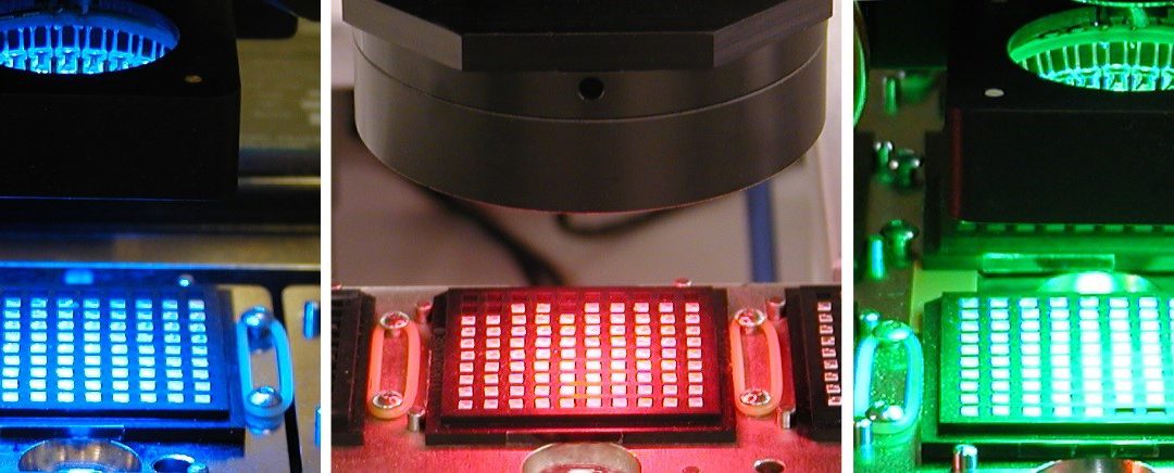
Multi-colored lighting is required to successfully vision process a wide range of materials. Tricolor (i.e., red, green, and blue) programmable lighting provides the capability for processing challenging alignment surfaces, such as gold traces on alumina. Lighting intensity must be programmable and include both ring and collimated lights for a complete lighting solution. It also must be possible to individually program optimal light settings for each die and substrate fiducial alignment.
Advanced vision must rapidly perform robust substrate fiducial alignment regardless of material contrast; and it should be able to detect and orient die over a full 360°. Both pattern recognition and boundary trace tools provide a complete solution to locate the die center, edges, or application-critical features. This enables fast, error-free processing of complex assemblies.
The optics and camera system must include multiple magnifications for both upward and downward facing cameras. Machine vision is used for alignment of components’ bottom features and flip-chips. An upward-facing camera captures the image of the die feature on the vacuum collet prior to placement. Software, hardware, lighting, and optics are integral. One example is the manufacturing of an AOC device. The downward facing camera first aligns the VCSELs on the substrate package. The upward facing camera aligns features on the bottom of the lens and the system places and bonds the device.
MRSI Systems continues to set the industry standard for ultra high-precision and high-speed die attach systems. More details here.
For more information please contact: sales@mrsisystems.com, 978-667-9449